| English | Japanese |
|
|
Yesterdays access |
| Page Top | [Lily Diary.】 A diary of life in Mindanao. |
| 25/12/28 | Article search now available on smartphones |
| 25/12/10 | KR-500 terminals Modification |
| 25/12/06 | Installation of satellite poles |
| 25/12/03 | Installing KR-500 on Kenpro KR-400 |
| 25/11/20 | Satellite tracking Sat Track - Development Version |
| 25/11/19 | Kenpro KR-400 arrived by EMS |
| 25/11/18 | 3.5MHz Antenna Toroidal Core |
| 25/11/16 | WiMO V/UHF Cross Yagi |
| 25/11/16 | WSJT-X Automatic operation Ver0.1.1 |
| 25/11/09 | Eyeball with DU9JJY in Cotabato |
| 25/11/04 | TNC software for APRSVer1.2 |
| 25/11/03 | Indonesian satellite IO-86 event |
| 25/10/29 | Active Satellite List |
| 25/10/24 | FTDX3000 repair completed |
| 25/10/17 | Kenpro KR-500 Repair Completed |
| 25/10/15 | ARISS SSTV DIPLOMA |
| 25/10/14 | International Space Station Information |
| 25/10/13 | ST2 interface for driving AC motor rotors |
| 25/10/12 | Received APRS signals from ISS |
| 25/10/11 | TNC software for APRS manual |
| 25/10/10 | TNC software for APRSVer1.0 |
| 25/10/09 | Making myopia glasses |
| 25/10/09 | ICOM IC-820H PLL UNLOCK repair |
| 25/10/05 | 435MHz Cross Yagi antenna production preparation |
| 25/10/04 | Receiving SSTV from the International Space Station |
| 25/10/03 | Repair of elevation rotator KR-500 |
| 25/10/02 | 145MHz Cross Yagi antenna production preparation |
| 25/10/01 | received APRS signal from ISS |
| 25/09/29 | CQ WW RTTY contest |
| 25/09/27 | SSTV from the ISS |
| 25/09/26 | WARC band fan-out antenna |
| 25/09/25 | levation rotator KR-500 acquired |
| 25/09/23 | APRS TNC software Dire Wolf with Hamlib |
| 25/09/23 | TNC software direwolf |
| 25/09/21 | Russian satellite RS-44 beacon |
| 25/09/20 | Installing a radio in a car |
| 25/09/17 | DH1NGP Peter radio vehicle |
| 25/09/13 | 3.5MHz SWR increased |
| 25/09/12 | 3.5MHz Zepp antenna adjustment |
| 25/09/10 | Geostationary satellite QO-100 |
| 25/09/09 | Preparing for the satellite station |
| 25/09/08 | DU9JJY satellite station |
| 25/09/07 | 14MHz late at night |
| 25/09/03 | Mitsubishi Strada Pickup Truck Oil Change |
| 25/08/18 | WSJT-X Automatic operation Ver0.1.0 |
| 25/08/18 | JTDX Autonomous operation Program Ver0.6.3 |
| 25/08/10 | Software List |
| 25/07/26 | AutoCWType_Ver1.5.8 |
| 25/07/20 | Create one month's worth of ADIF files from JTDX Ver 2.6.5 |
| 25/07/19 | Japan's Radio Wave Usage Tax |
| 25/07/13 | IARU HF Contest |
| 25/07/10 | Software updates |
| 25/07/08 | DXV500ZS linear amplifier repair |
| 25/07/07 | CQ Machine Program |
| 25/06/21 | LoTW system upgrade |
| 25/06/18 | RG8 for 3.5MHz arrived |
| 25/06/15 | Time setting Ver0.5 |
| 25/06/14 | Drone Habsan ZINO arrives |
| 25/06/12 | Philippine Independence Day |
| 25/06/11 | Algeria 7X2RF QSL card. |
| 25/06/10 | Translation API Program |
| 25/06/09 | DXCC150 award certificate arrived |
| 25/06/08 | AutoCWType_Ver1.4.1 |
| 25/06/07 | Introducing the Shack |
| 25/06/06 | A portrait drawn by ChatGPT. |
| 25/05/26 | Windows full-width/half-width switching. |
| 25/05/17 | OK2ZAW BCD to 16 converter. |
| 25/05/16 | For 3.5MHz Zepp antenna. Stepping motors |
| 25/05/15 | 3.5MHz stepping motor design. |
| 25/05/14 | 3.5MHz tuning coil installed. |
| 25/05/11 | 3.5MHz antenna installation completed. |
| 25/05/03 | JTDX Autonomous Driving Program Ver0.4.3. |
| 25/04/26 | Drone Habsan ZINO. |
| 25/04/25 | Time setting Ver0.3. |
| 25/04/24 | AutoCWType_Ver1.3. |
| 25/04/23 | Preparing for FTDX3000 LCD repair. |
| 25/04/22 | Installation plan for 3.5MHz Zepp antenna. |
| 25/04/21 | AutoCWType_Ver1.1. |
| 25/04/20 | 10,14MHz antenna installation completed. |
| 25/04/19 | JTDX Autonomous Driving Program Ver0.4.1. |
| 25/04/19 | 14MHz antenna pole installed. |
| 25/04/18 | ThinkPad X390 repair completed. |
| 25/04/17 | Search is now possible. |
| 25/04/15 | Preparing the 10MHz dipole. |
| 25/04/12 | Hexbeam Part8. |
| 25/04/06 | My ThinkPad X390 is broken. |
| 25/04/05. | Time setting program. |
| 25/03/31 | JTDX Autonomous Driving Program. |
| 25/03/30 | Automatic log sending from CWType to Hamlog. |
| 25/03/21 | Hexbeam Part 7. |
| 25/03/20 | FreeDV Part 3 First QSO. |
| 25/03/18 | FreeDV Part 2 QSO in the shack. |
| 25/03/16 | Hexbeam Part 6. |
| 25/03/15 | Install FreeDV Part1. |
| 25/03/09 | Hexbeam Part5. |
| 25/03/07 | Hexbeam Part 4. |
| 25/03/05 | 28MHz antenna modification |
| 25/03/01 | FTDX3000 is broken! |
| 25/02/28 | Pileup at 50MHz FT8. |
| 25/02/28 | DXV500ZS linear amplifier repair. |
| 25/02/27 | Tower pipe rebuilding plan. |
| 25/02/26 | Direction to Japan from Ozamiz. |
| 25/02/26 | 28MHz is not available. |
| 25/02/23 | DXV500ZS linear amplifier repair. |
| 25/02/22 | Hexbeam Part 3 |
| 25/02/21 | Hexbeam Part 2 |
| 25/02/18 | 28MHz antenna construction. |
| 25/02/17 | 18,24MHz antenna height construction. |
| 25/02/16 | Z26NS Cosovo. |
| 25/02/14 | 21MHz FT8 |
| 25/02/12 | 7,21MHz antenna repair. |
| 25/02/08 | Operating CW at 21MHz. |
| 25/02/05 | DXV500ZS linear amplifier failure. |
| 25/01/19 | Input Director. |
| 25/01/14 | Temporary license renewal. |
| 28MHz antenna modification (2025/03/05) | |||||||||||||||||||||||||||||
|---|---|---|---|---|---|---|---|---|---|---|---|---|---|---|---|---|---|---|---|---|---|---|---|---|---|---|---|---|---|
| 28MHz antenna installed on February 18th 7.21MHz dipole as a fan-out dipole antenna A 28MHz element was installed, and the 28MHz element was inverted V to allow for element spacing. However, I found out that if you place it next to the parent element (7, 21MHz) and leave a gap of about 10cm, there will be no effect. 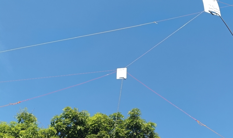 |
|||||||||||||||||||||||||||||
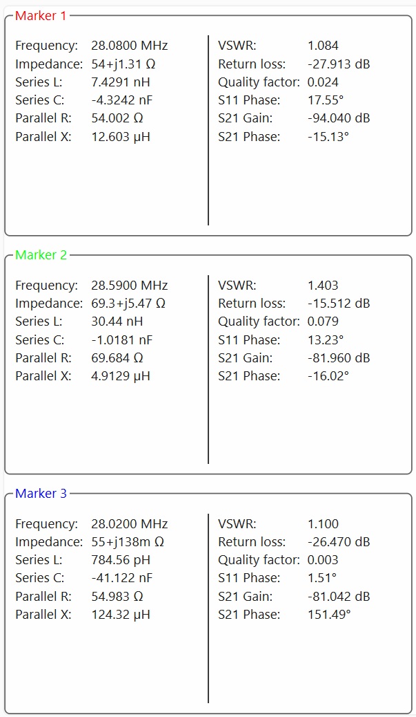
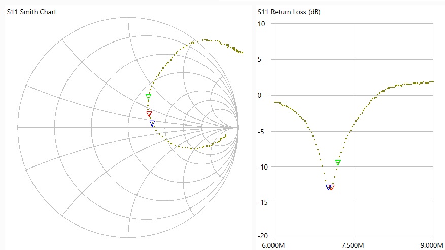
| It is attached to the 7.21MHz parent element with a 10cm corrugated insulator. The length of the element was measured with a NanoVNA to be 2.30m, with the SWR settling at 28.110MHz. Element length (one side): (300/28.110)/4*0.95=2.53I calculated it to be 100m, but it actually turned out to be much shorter. I ordered the corrugated insulators from Japan on Amazon. 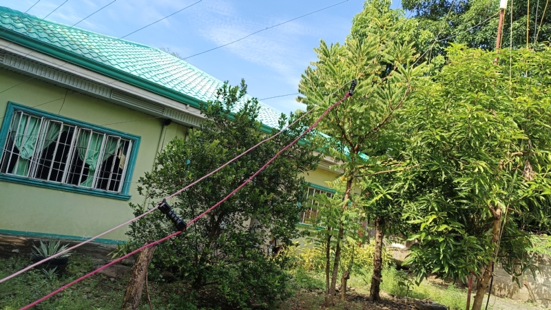 |
|||||||||||||||||||||||||||||
| The 28MHz element was changed from an inverted V to a dipole. The height above ground is now about 18m. We received many calls from Europe, a place where no one had answered our calls before. Maybe the increased ground clearance helped. 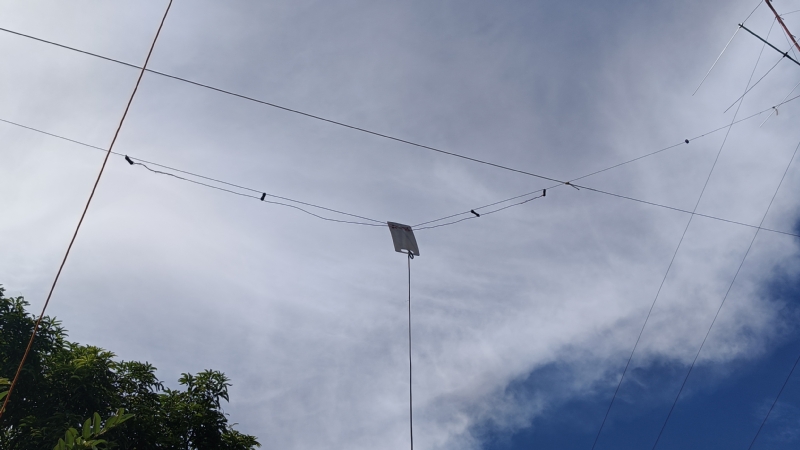 |
|||||||||||||||||||||||||||||
Measurement with NanoVNA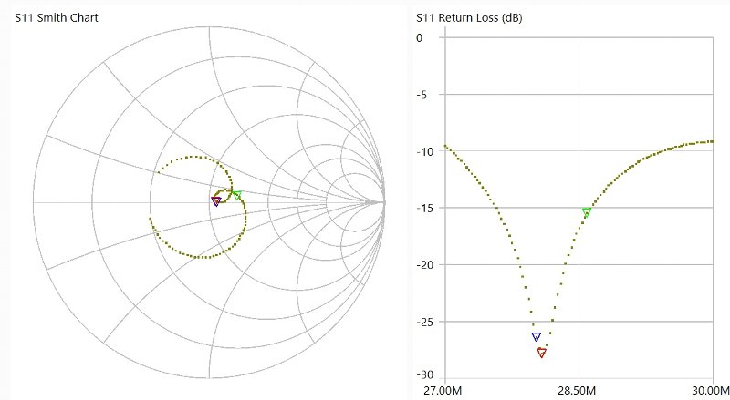
| |||||||||||||||||||||||||||||