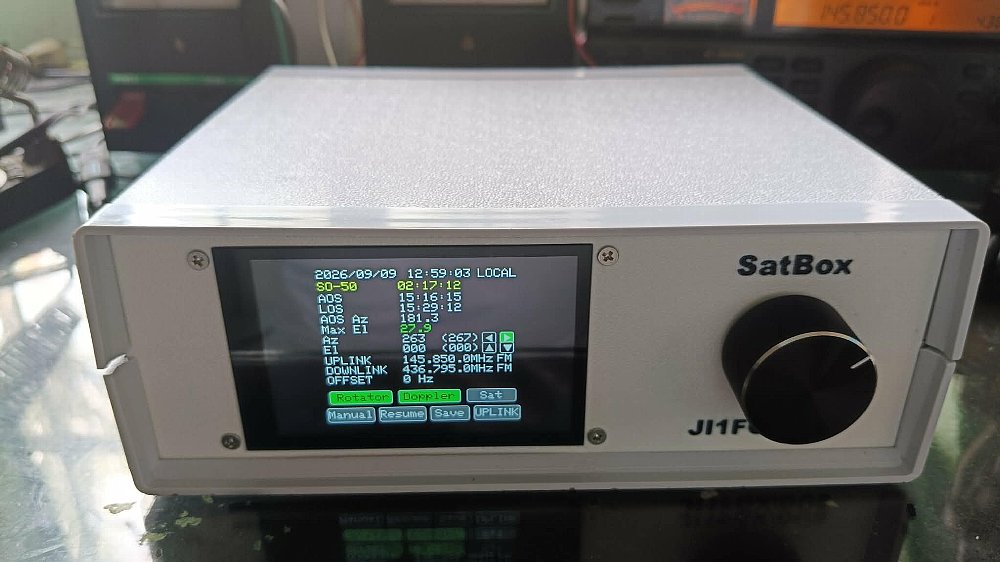
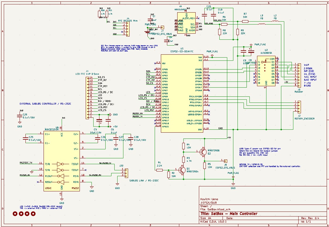
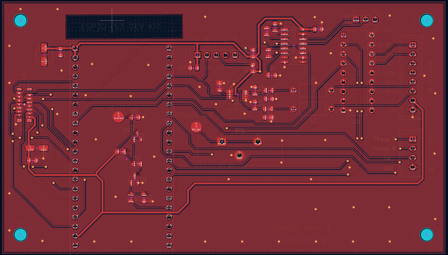
SatBox Ver0.1.1c — Beta test setup
SatBox is an ESP32-S3 satellite controller developed by JI1FGX/DU9. It provides satellite predictions, antenna rotator control and radio frequency/mode control for satellite operation. Most settings and operations are available through the PC settings program and a Web browser; a local LCD is optional.
Thank you to the AMSAT Facebook group members who have offered to test SatBox. This release shares the current firmware source and KiCad circuit/PCB data for evaluation. It is a development version, and feedback is welcome.
Comments are written in English and Japanese wherever possible, but some comments may be in Japanese only.
Test status
| Radio / hardware |
Connection |
Status |
| ICOM IC-820H |
ESP32-S3 USB host port → OTG adapter → FTDI USB-to-RS-232C adapter using the FT232C IC |
Currently checked by the author; only this adapter configuration is supported for testing |
| Yaesu FT-847 |
SatBox RS-232C port → radio CAT port |
Currently checked by the author |
| ICOM IC-9700 |
SatBox RS-232C port → CT-17 or equivalent → radio REMOTE jack |
Code implemented; not yet tested with an actual IC-9700 |
| IC-9700 via USB / FTDI |
USB connection |
Not implemented; selecting this combination does not start CAT control |
| KiCad PCB design |
Published schematic and PCB data |
Not ordered from JLCPCB yet; no assembled-PCB operation has been verified |
IC-9700 code may contain bugs. Please report any incorrect behavior to JI1FGX/DU9, including how to reproduce it. Software simulation tests do not establish actual radio compatibility. A working prototype does not establish that the published PCB layout works.
The existing USB option is labelled USB (FT232B) in the settings page. The supported IC-820H test adapter is the FT232C configuration described above; the label does not imply support for other FTDI chips, CH340, CP210x or the IC-9700's built-in USB interface.
1. Equipment
| Item |
Needed for |
| ESP32-S3 board, suitable power supply and programming/data cable |
All tests; use a board exposing the pins and USB host connections in the schematic |
| DS3231 RTC module with backup battery |
The standard test setup; maintains time when network time is unavailable |
| PC and 2.4 GHz Wi-Fi network |
Initial setup; use a browser on the same LAN for Web operation |
| MAX3232 or equivalent 3.3 V-compatible RS-232C level-converter module |
FT-847 and IC-9700 RS-232C tests |
| FTDI FT232C USB-to-RS-232C adapter and OTG adapter |
Supported IC-820H USB tests |
| CT-17 or equivalent CI-V interface |
IC-9700: converts the RS-232C connection to the radio's REMOTE interface |
| ADS1115 module |
Reading the rotator's analog AZ/EL position signals |
| ULN2803A driver circuit |
Rotator control outputs |
| External relay interface |
Controlling an AC-motor rotator |
| 3.5-inch ST7796S LCD panel; FT6336 touch if used |
Optional local display/touch operation |
An LCD is not required for testing. You can start with ESP32-S3, RTC, PC and Wi-Fi, then add a radio and finally the rotator circuitry. ADS1115 and motor-output hardware are required only for the corresponding rotator tests. The absence of a display does not remove the firmware's TFT library dependency.
2. Wiring
Use the KiCad schematic together with Pin.h. The PCB layout is unverified; check module pinouts, power rails, connector orientation and signal levels against the actual parts before building it.
RS-232C / radio connection
The FT-847 and IC-9700 share UART1 pins and are selected exclusively in software:
| ESP32-S3 pin |
Connection |
| GPIO15 / RX |
MAX3232 logic-side receiver output (RO): data arriving from the radio/interface |
| GPIO16 / TX |
MAX3232 logic-side transmitter input (DI): data going to the radio/interface |
| GND |
Level-converter logic ground; complete signal-ground wiring according to the schematic |
An RS-232C level-converter module is necessary. Never connect RS-232C voltage directly to an ESP32-S3 GPIO. Use the module's RS-232C side for the external port; follow the radio/interface pinout for the cable.
- FT-847: RS-232C port to the radio CAT port. UART1 uses 8N2. Match the baud rate on both ends (4800 / 9600 / 57600 bps).
- IC-9700: RS-232C port to CT-17 or equivalent, then to the REMOTE jack. UART1 uses 8N1. Match the radio's CI-V baud rate and address. For this REMOTE/CT-17 path use 4800 / 9600 / 19200 bps; default CI-V address is A2h. Higher speeds visible in the UI are not for this REMOTE test path.
- GPIO15/16 are also assigned to future SA818 UHF use in
Pin.h; do not connect competing UART devices to them at the same time.
IC-820H USB connection
Connect the FTDI FT232C USB-to-RS-232C adapter to the ESP32-S3 USB host/OTG port through an OTG adapter. Complete the radio-side interface wiring according to the schematic and your checked IC-820H setup. A USB-to-TTL adapter is not a substitute for a USB-to-RS-232C adapter.
The USB host port is separate from the PC programming/settings serial connection. The firmware controls USB VBUS power through GPIO21; reproduce the schematic's VBUS switching circuit. GPIO21 is a control signal, not a USB power supply. Keep the host port available for the FTDI adapter while using the board's separate USB-to-UART programming port for PC settings, where available.
RTC, position input and rotator output
| Signal |
Current assignment |
| Shared I2C SDA / SCL |
GPIO1 / GPIO2 |
| RTC |
DS3231 on the I2C bus |
| Position ADC |
ADS1115, I2C address 0x48 |
| Elevation / azimuth analog input |
ADS1115 A0 = EL, A1 = AZ |
| AZ clockwise / counterclockwise outputs |
GPIO47 / GPIO45 |
| EL up / down outputs |
GPIO35 / GPIO36 |
Use the schematic's voltage-divider/input circuit for the rotator feedback signals. The firmware assumes a 15 kΩ / 22 kΩ divider; do not connect an unknown rotator feedback voltage directly to the ADS1115. Verify the ADC input stays within the powered module's limits.
Use ULN2803A for the control-output driver stage. Do not drive a motor from an ESP32 pin. An AC-motor rotator requires a separate relay interface:
Before motor tests, calibrate AZ/EL position inputs through the Web calibration page and check each direction with short manual operations.
Optional LCD
The panel is LCD ST7796S, 3.5 inch. Current SPI wiring is CS=10, DC=9, RST=14, MOSI=11, MISO=13, SCK=12, backlight control=8. Optional FT6336 touch uses the shared I2C bus, RST=3 and INT=4. Consult the schematic for panel power and connector pin numbering. Leave the panel disconnected for LCD-free tests; no LCD-free firmware variant is required.
3. Build and upload the firmware
- Keep the sketch folder named
SatBox_Ver0.1.1c-beta and open SatBox_Ver0.1.1c-beta.ino in Arduino IDE. Keep the root .cpp / .h files and tft_setup.h together with the sketch. The .ino file alone is not the whole program.
- Install the Espressif ESP32 board package and select the actual ESP32-S3 board. Use the board's real flash/PSRAM sizes and a partition layout with enough application space and a filesystem. The local build records used ESP32-S3 with Huge APP and Arduino-ESP32 3.3.8; they do not establish a successful build of this complete revision.
- Install the libraries below, including their dependencies. These are the versions found in the author's local environment, not a fully validated compatibility matrix.
- Keep
tft_setup.h for the ST7796S configuration. TFT_eSPI 2.5.43 supports the sketch-local setup used here. This dependency is needed even when no panel is fitted.
- Compile and upload through the board's programming port. The native USB peripheral is used as a host for FTDI operation; do not assume the same native USB port can simultaneously provide a PC USB-CDC settings connection. Use the board's USB-to-UART port where available.
- Open the serial monitor at 115200 bps to check startup, then close it before opening the PC settings program.
Arduino IDE Tools settings
Use the following settings for the author's 4 MB configuration shown in the setup screenshots:
| Tools menu item |
Setting |
| Partition Scheme |
Huge APP (3MB No OTA/1MB SPIFFS) |
| Flash Mode |
QIO 80MHz |
| Flash Size |
4MB (32Mb) |
The partition menu name includes “SPIFFS”; the firmware uses LittleFS in the filesystem partition. Keep the partition selection above. This layout allocates 3 MB to the application and does not provide OTA update space. Use these flash settings with hardware matching the author's configuration.
| Arduino library |
Version found locally |
| TFT_eSPI |
2.5.43 |
| RTClib |
2.1.4 |
| Adafruit ADS1X15 |
2.6.2 |
| Adafruit BusIO |
1.17.4 |
SparkFun SGP4 Arduino Library (Sgp4.h) |
1.0.4 |
| ReadyMail |
0.4.2 |
Wi-Fi, WebServer, Wire, LittleFS and USB host headers come from the ESP32 platform. A separate generic FTDI Arduino library is not used: this project includes its own FTDI.cpp / FTDI.h.
Build status: the IC-9700 implementation notes record a full ESP32 build attempt blocked by a Windows Illegal System DLL Relocation compiler-startup error. Host simulation tests passed according to those notes, but do not replace a complete firmware build or hardware testing. Report build failures with the board/core/library versions and full error output.
4. Initial configuration without an LCD
Use Python 3.10 or later, with Tkinter and pyserial. From the project's software directory:
python -m pip install pyserial
python SatBox_Settings.py
Run the tool from software so that its local settings.ini stays there.
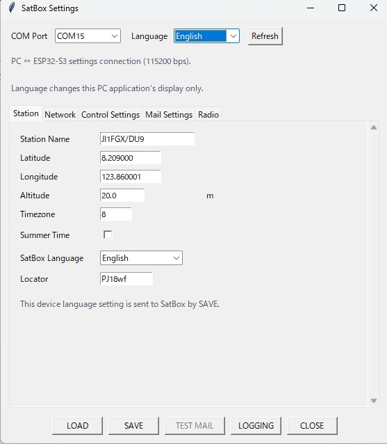
- Connect the PC to the ESP32-S3 programming/settings serial port. Close Arduino Serial Monitor and other programs using that port.
- Select the COM port (use Refresh if needed), then press LOAD to read the device's settings.
- Set Wi-Fi SSID/password, hostname, station name, latitude/longitude/altitude, time-zone offset and daylight-saving setting. Use your own station data. DHCP is a convenient starting point.
- Press SAVE and allow Wi-Fi reconnection/startup to finish. Press LOAD again to check Current IP. If necessary, restart SatBox and check again. The PC settings connection is 115200 bps, independently of the radio baud rate.
- On a PC or phone on the same LAN, open
http://<Current IP>/. With the default hostname and working mDNS, http://satbox.local/ can also be used.
- Use the Web Setup menu for the remaining settings. You can configure the IC-9700 model, COM (RS-232C) connection, CI-V baud rate and address either on the Web radio page or in the radio tab of the PC settings application (SatBox_Settings.py). For IC-9700, select COM and connect a CT-17 or equivalent to the REMOTE jack. USB/FTDI control is not implemented.
| Web page |
Purpose |
/ |
Satellite display and main operation |
/setup |
Setup menu and language selection |
/network, /station |
Network and station settings |
/radio |
Radio model, connection, baud rate and CI-V address; restart after saving radio changes |
/satsetup, /tledownload |
Satellite selection and TLE update |
/dopplersetup |
Satellite frequency/mode data, stored as /doppler.csv in LittleFS |
/offsetsetup |
Per-radio/per-satellite offsets |
/calibration |
Rotator position calibration |
/control |
Tracking/control and alert settings |
| /settings-restore |
Restore All Settings |
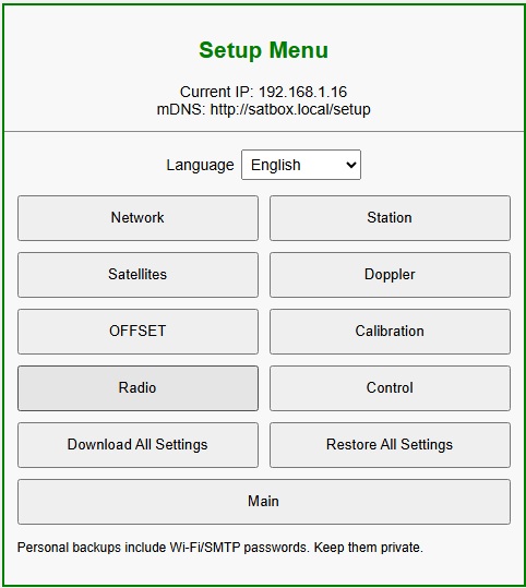
Check current date/time and station coordinates before judging orbit predictions.
Provide internet access for the initial TLE download and NTP time synchronization;
confirm TLE data is available. RTC maintains time, while saved TLE data
can support later offline tests. Set frequency/mode data for the satellites
you intend to test.
Most operation is possible using the PC tool and Web pages, so testers do not need the LCD or local touch/encoder controls. A PC log server is not required for basic radio/rotator tests; it is a separate feature.
5. Suggested test order
- Start with motor outputs disconnected: confirm boot, PC LOAD/SAVE, Wi-Fi, Web access, time and TLE availability.
- Configure the radio on
/radio, match its settings and restart SatBox. For IC-9700, choose COM (RS-232C) and use the CT-17/REMOTE path; do not select USB.
- Check satellite preset frequencies/modes, TX/RX band assignment, manual receive operation, Doppler updates and recovery after the radio is powered off/on. Begin with receive/control checks before any intended transmission.
- For IC-9700 satellite mode, actual MAIN = RX, SUB = TX. Confirm that frequency changes affect the intended side and report unintended movement of the other side. Initial coverage is 144/430 MHz satellite operation; 1200 MHz, DV/DD, memories, CAT PTT and radio power on/off are outside this implementation.
- Add ADS1115 feedback, verify angles and calibrate endpoints. Then add ULN2803A and the required motor/relay interface, check short manual movement and finally tracking.
- Note whether the test used a wired prototype or the published PCB, and whether the LCD was fitted.
6. Reporting problems
Please report problems directly to JI1FGX/DU9, using the AMSAT Facebook post/message thread where you joined the test, or email du9@ji1fgx.com. Reports from IC-9700 testers are especially valuable because that code has not been tested on an actual radio.
Include:
- Firmware version/revision and test date.
- ESP32-S3 board, flash/PSRAM, Arduino core/library versions and build settings.
- Radio model/firmware, connection diagram, interface/adapter model and chip, baud rate and CI-V address.
- LCD fitted or absent; RTC/ADS1115/rotator hardware used.
- Satellite, time, relevant frequencies/modes, exact steps, expected result and actual result.
- Serial log at 115200 bps, screenshots or a short video, and whether the issue is repeatable or recovers after restart.
Remove Wi-Fi passwords, mail credentials and other private information from logs and screenshots before sending them.
7. Public hardware files
KiCad schematic and PCB data are shared for review and experimental construction. The PCB has not yet been ordered from JLCPCB, assembled or functionally verified. Please review the design before ordering boards, and report schematic/layout errors as well as firmware issues. The relay-interface product is separate from the SatBox PCB.
As I am living on a pension, I have not yet been able to cover the approximately US$95 cost of ordering the PCB from JLCPCB. Donations to help fund development would be greatly appreciated. PayPal: du9@ji1fgx.com
Documentation prepared: 2026-11-06. See IC9700_CI-V_Implementation_Notes_EN.md and CHANGELOG_EN.txt.