| English | Japanese |
Yesterdays access |
|
| Page Top | [Lily Diary.】 A diary of life in Mindanao. |
| 26/11/07 | SatBox_Ver0.1.1c-beta IC-9700 Test Version |
| 26/11/07 | SatBox User Guide |
| 26/10/27 | Repeater Controller Features and Settings |
| 26/10/27 | Repeater Controller Board and Firmware |
| 26/10/26 | JTDX Auto Run Ver0.7.7 |
| 26/10/26 | WSJT-X Auto Run Ver0.1.6 |
| 26/10/18 | Kenpro Rotator Relay Interface – Revised Version |
| 26/09/22 | Kenpro Rotator Interface |
| 26/09/18 | SatBox KiCad PCB and firmware |
| 26/06/01 | Weather Monitor soft |
| 26/05/21 | JTDX Auto Run Ver0.7.6 BUGFIX |
| 26/04/08 | ESP32-S3 software for using KENWOOD AT-300 with YAESU radios |
| 26/01/04 | log_reciver_Ver2.6.6 software |
| 25/11/04 | APRS TNC software Ver1.2 |
| 25/10/10 | APRS TNC software Ver1.0 |
| 25/09/23 | APRS TNC software Dire Wolf with Hamlib |
| 25/08/10 | Software List |
| 25/07/20 | A program to create one months worth of ADIF files from JTDX Ver2.6.5 |
| 25/07/13 | CQ Machine Program Ver1.5_2 |
| 25/07/10 | AutoCWType_Ver1.4.5 |
| 25/06/10 | Google, DeepL translation API |
| Repeater Controller Board and Firmware (October 27, 2026) | |||||||||||||||||||||||||||||||||||||||||||||||||
|---|---|---|---|---|---|---|---|---|---|---|---|---|---|---|---|---|---|---|---|---|---|---|---|---|---|---|---|---|---|---|---|---|---|---|---|---|---|---|---|---|---|---|---|---|---|---|---|---|---|
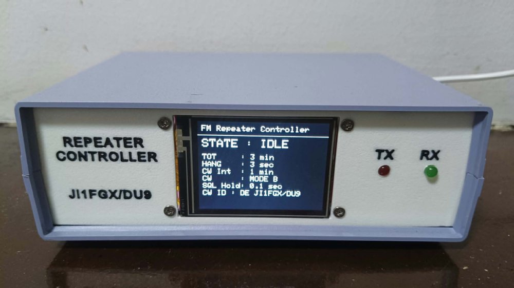
This page introduces the board and firmware for an ESP32-S3-based FM repeater controller.
For shipping costs, please contact us at the email address below. du9@ji1fgx.com |
|||||||||||||||||||||||||||||||||||||||||||||||||
  |
|||||||||||||||||||||||||||||||||||||||||||||||||
| Analog Audio Mixer Circuit This circuit combines receiver audio, CW tones generated by the ESP32-S3, and voice ID audio from the DFPlayer, and feeds the combined signal to the transmitter microphone input. 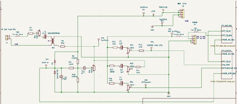 |
|||||||||||||||||||||||||||||||||||||||||||||||||
PCB designed in KiCad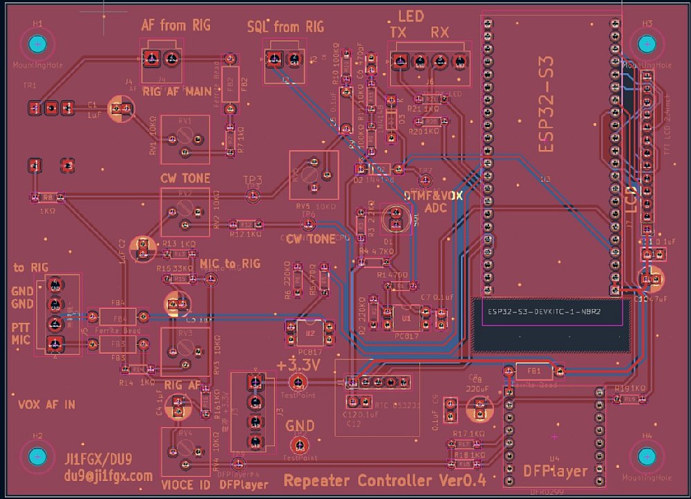 |
|||||||||||||||||||||||||||||||||||||||||||||||||
PCB manufactured by JLCPCB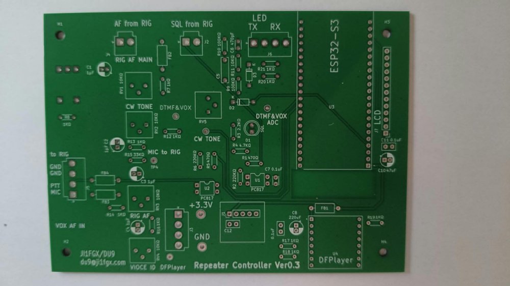 |
|||||||||||||||||||||||||||||||||||||||||||||||||
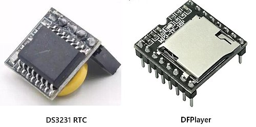
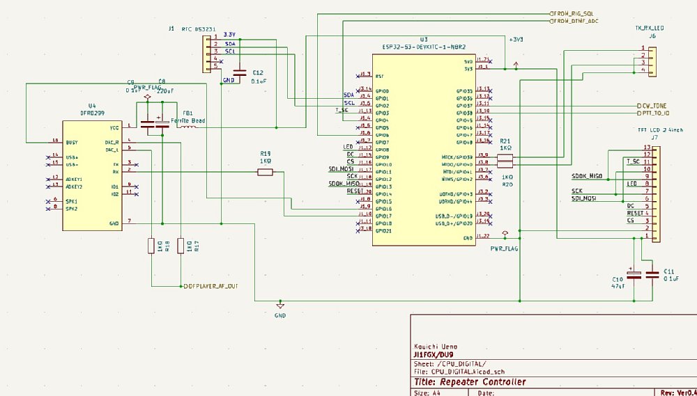
| Assembled board The analog audio mixer is on the left, the ESP32-S3 is on the right, and the RTC and DFPlayer are at the bottom. VOX (voice-operated transmit control) was initially implemented using an op-amp circuit. Because the circuit frequently triggered incorrectly, VOX was changed to a software implementation. DTMF (touch-tone) decoding is also performed in software. 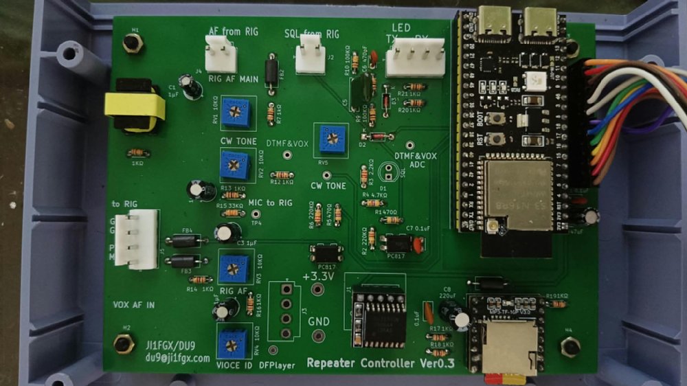
|
|||||||||||||||||||||||||||||||||||||||||||||||||
| Board Modification for Repeater Controller Ver0.3 The Ver0.3 board requires one jumper wire. Connect a jumper wire from the cathode of diode D3 to pin 1 of the RTC connector J1. This issue has been corrected in the Repeater Controller Ver0.4 board. 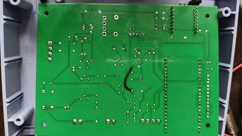 |
|||||||||||||||||||||||||||||||||||||||||||||||||
| September 30, 2026 October 2, 2026 | |||||||||||||||||||||||||||||||||||||||||||||||||