| Kenpro Rotator Interface — Design File Downloads | |||||||||||
|---|---|---|---|---|---|---|---|---|---|---|---|
KiCad Design Files for DIY Construction and EvaluationThis relay interface allows a controller such as SatBox or the Fox Delta ST2 to control a Kenpro AC motor rotator. This page provides the schematic, PCB data, and KiCad library for download. Download the design files / How to use the files To purchase a bare PCB or an assembled board, please visit the Rotator Relay Interface sales page for prices, available options, and contact details. Important Notice for Ver1.1 UsersThere was a serious error in the Ver1.1 PCB layout. I apologize for the inconvenience. Please use the Ver1.2 design files below for new builds and PCB orders. If you have already made a board using Ver1.1, compare it with the Ver1.2 schematic and PCB data and check the wiring before applying power. If anything is unclear, contact me by email with the version used and details of your board. A relay interface is therefore required to control them using the Fox Delta ST2 or SatBox. 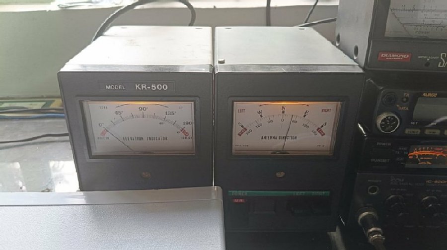 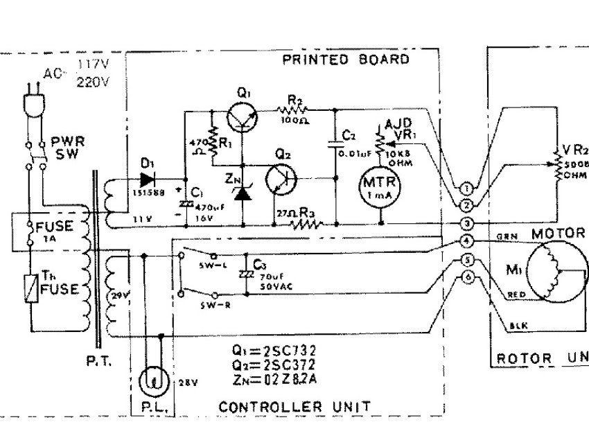
|
|||||||||||
How to Use the Downloaded Files
Before Assembly and ConnectionOperation has been tested with the Kenpro KR-400 and KR-500. For other models, check the motor drive voltage, terminal assignments, control method, and relay contact ratings. The required power supply circuitry differs depending on whether you use the original potentiometer or replace it with an AS5600 magnetic encoder. Refer to the board description below and the related construction article to confirm the configuration you need. Disconnect power before wiring. Check for short circuits, correct component polarity, and correct connector wiring before applying power. When testing with the rotator, verify the direction of rotation and stopping operation before use. Download Problems and InquiriesIf saving does not begin after clicking a link, check your browser's download history and any error messages. If the problem continues, email JI1FGX/DU9 with the file name and the error shown. For construction questions, include the design file version, KiCad version, and the model numbers of your rotator and controller. Comments below this article are published after approval; please do not include personal information such as your address or telephone number. | |||||||||||
This relay interface connects SatBox to a Kenpro rotator.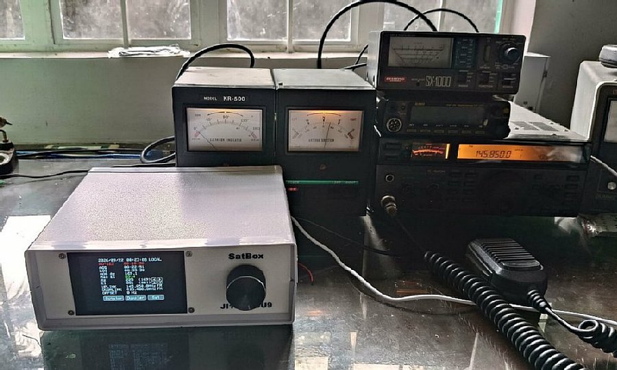 |
|||||||||||
The interface uses four SRA-05VDC-CL relays.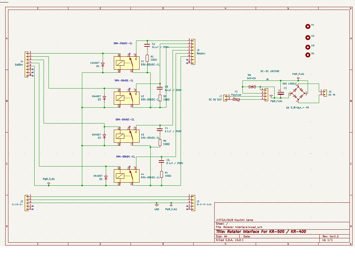 |
|||||||||||
|
This is an interface board designed with KiCad. It has already been ordered from JLCPCB. Note: The DC-DC LM2590 circuit on the right side is normally not required. It is used only when replacing the potentiometers inside the rotator with AS5600 magnetic encoder angle sensors. https://ji1fgx.com/en/260604.html 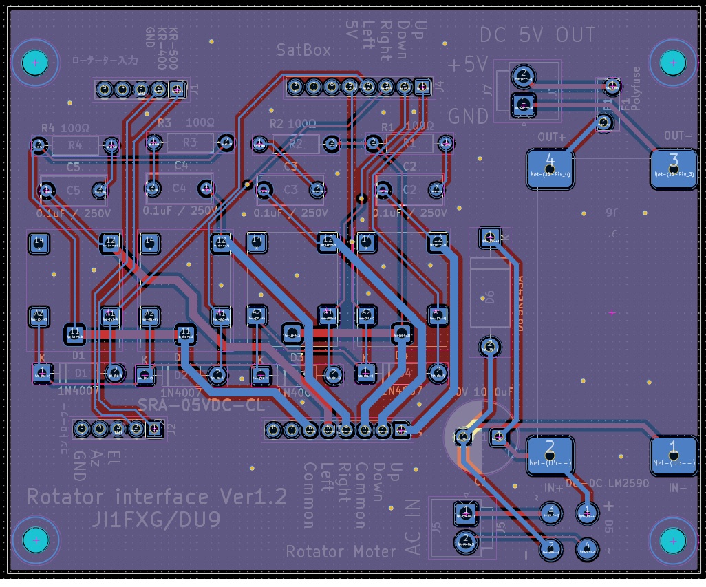 |
|||||||||||