| Repeater Controller Features and Settings |
Repeater Controller Touchscreen Display
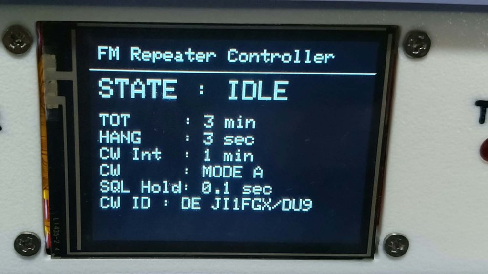
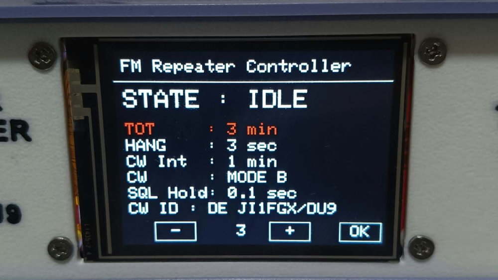
Standby (STATE: IDLE)
The controller is waiting for an incoming signal. The display shows the current TOT, HANG, CW ID, and other settings.
|
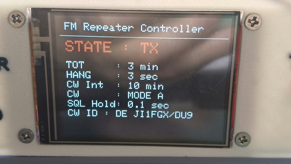
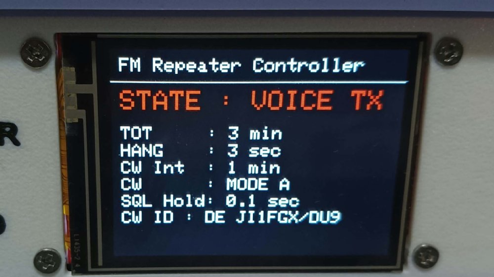
Repeating an Incoming Signal (STATE: TX)An incoming signal has been detected on the receiver (uplink), and the transmitter (downlink) PTT is activated to relay it.
|
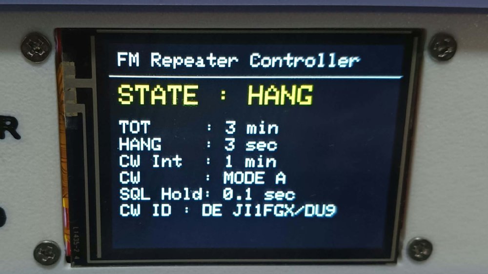
Transmit Hold (STATE: HANG)
Transmission continues for the configured HANG time after the received signal ends. If another signal arrives during this period, normal repeating resumes.
|
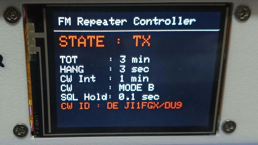
Transmitting a CW IDThe configured message, such as your call sign, is transmitted in Morse code.
|
Transmitting a Voice ID
The DFPlayer plays audio files for the time signal, spoken time, and call sign.
Sample audio files are provided. Prepare suitable recordings for your own station.
|
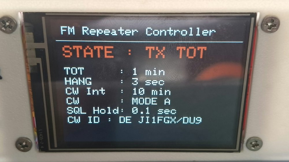
TOT (Time-Out Timer): Limiting Continuous TransmissionWhen the time limit is reached, transmission stops and the controller enters TOT lockout.
The controller returns to standby after the receive input remains inactive for the TOT_LOCK period.
|
Settings Screen
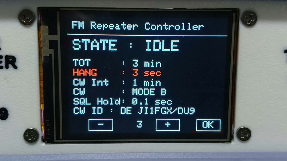
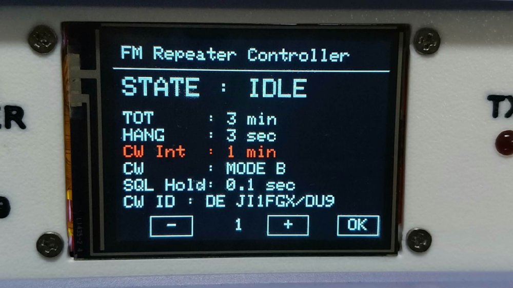
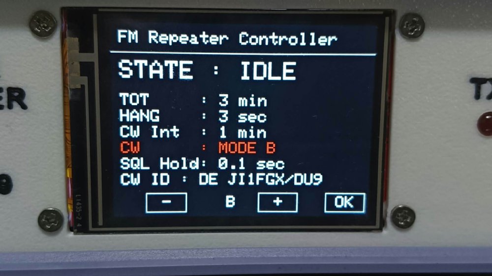
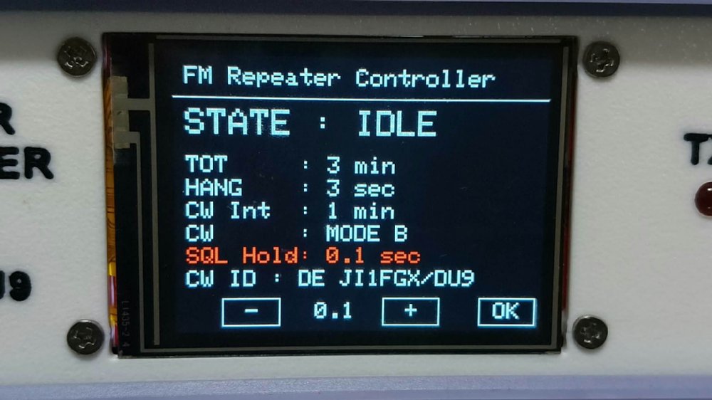
Tap an item while the controller is idle to edit it. The selected item turns red. Use [-] and [+] to change the value, then tap [OK] to save.
Repeater operation is suspended while editing settings on the touchscreen.
TOT: Continuous transmission limit, adjustable from 1 to 30 minutes.
|
Transmit Hold Time (HANG)
The transmit hold time after reception ends can be set from 0 to 30 seconds.
|
CW ID Interval
Select OFF, 1 minute (for testing), or 5, 10, 15, 30, or 60 minutes.
The firmware suppresses CW at minute 00 to give priority to voice ID.
Check the actual transmission timing on your controller when using the
60-minute setting.
|
CW MODE
| Choose MODE A or MODE B for CW ID transmission. |
| MODE A |
After the configured CW interval has elapsed, a CW ID is transmitted in response to repeater access. |
| MODE B |
CW IDs are transmitted periodically using the RTC clock, CW interval, and CWID_START settings. |
|
Receive Signal Qualification Time (SQL HOLD)
The receive input must remain active for this period before transmission starts. This helps prevent brief noise bursts from triggering unwanted transmissions.
On the touchscreen, this can be set from 0 to 5.0 seconds in 0.1-second steps.
In the PC settings editor, SQL_STABLE uses units of 100 ms: for example, 3 means 0.3 seconds and 50 means 5.0 seconds.
|
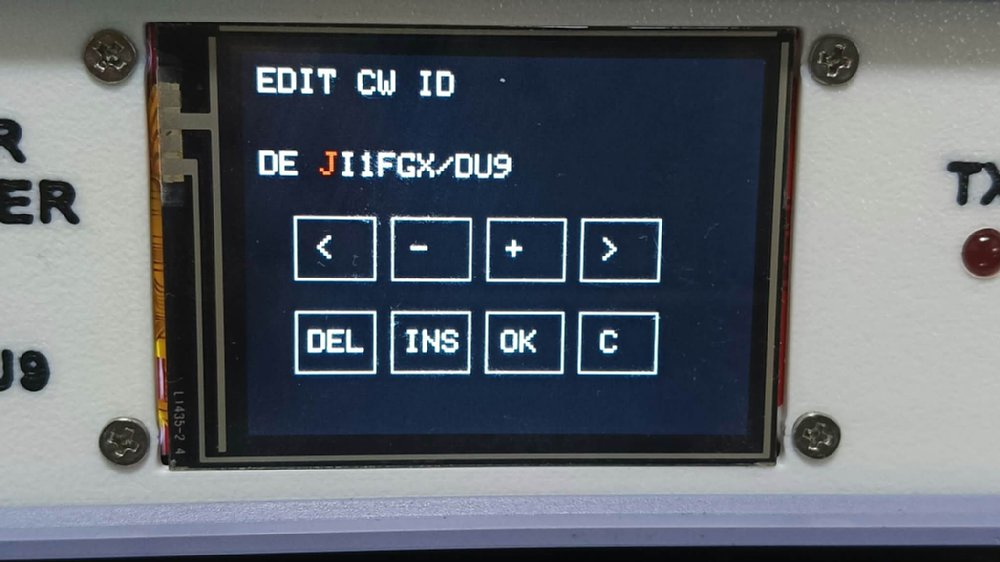
Editing the CW ID MessageUse the left and right arrows to select a position, and [-] and [+] to change the character. [INS] inserts a space and [DEL] deletes a character.
Tap [OK] to save or [C] to cancel. Enter up to 19 characters using uppercase letters, digits, spaces, and /.
|
Repeater Controller PC Settings
Use the Windows settings editor Repeater_Controller_Settings.exe to read and change the settings of a controller connected via USB.
The touchscreen provides access to the main settings.
The PC settings editor lets you edit the detailed settings below and save them to the controller EEPROM.
After connecting via USB, select the COM Port and click [Load] to read the current settings. After editing, click [Save] (the middle button).
Close other programs using the same COM port, including the Arduino IDE Serial Monitor.
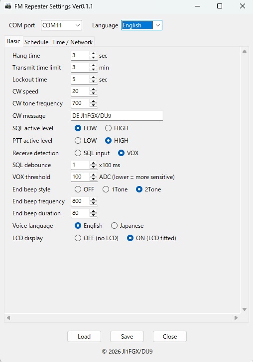
PC Settings ReferenceThe values in the screenshot are examples, not defaults or recommended values. Check the time units carefully: minutes, seconds, or 100 ms. Basic Settings| Screen Label | Description and Settings |
|---|
| COM port | The COM port used for the USB connection. Select the port assigned to the connected ESP32-S3. |
|---|
| Language | Select the display language. Choose English for the labels shown in these screenshots. |
|---|
| Hang time | Transmit hold time after reception ends, in seconds. Corresponds to HANG on the touchscreen. |
|---|
| Transmit time limit | Continuous transmission limit, in minutes. Corresponds to TOT on the touchscreen. |
|---|
| Lockout time | After TOT stops transmission, the receive input must remain inactive for this number of seconds before lockout is released. |
|---|
| CW speed | CW speed in words per minute (WPM). Higher values produce faster Morse code. |
|---|
| CW tone frequency | CW tone frequency in Hz. For example, 700 means 700 Hz. |
|---|
| CW message | The CW message, such as your station call sign. Use alphanumeric text, up to 19 characters. |
|---|
| SQL active level | Active polarity of the external squelch input. Select LOW or HIGH to match the receiver SQL output. |
|---|
| PTT active level | PTT output polarity during transmission. Select LOW or HIGH to match the connected PTT interface. |
|---|
| Receive detection | SQL input: Detect reception using the external squelch signal.
VOX: Detect incoming audio in software. |
|---|
| SQL debounce | Receive input qualification time.
The value is multiplied by 100 ms (0.1 seconds). For example, 1 = 0.1 seconds and 10 = 1 second. |
|---|
| VOX threshold | Audio detection threshold in ADC units. Lower values increase sensitivity. |
|---|
| End beep style | HANG end tone style. OFF: none; 1tone: one tone; 2tone: two tones. |
|---|
| End beep frequency | Base frequency of the HANG end tone, in Hz. |
|---|
| End beep duration | HANG end tone duration setting in ms. For example, 80 = 0.08 seconds. |
|---|
| Voice language | Voice announcement language. Select English or Japanese. Matching audio files are required. |
|---|
| LCD display | Select OFF (no LCD) or ON (LCD fitted) to match the controller hardware. |
|---|
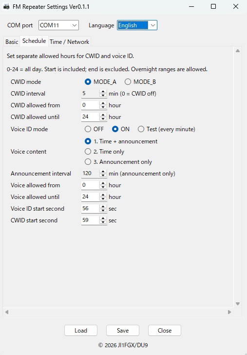
Schedule| Screen Label | Description and Settings |
|---|
| CWID mode | MODE_A: Transmit in response to access after the interval has elapsed. MODE_B: Transmit periodically according to the clock. |
|---|
| CWID interval | CW ID interval in minutes. 0 means OFF. |
|---|
| CWID allowed from / CWID allowed until | Allowed CW ID transmission hours. Start is included; end is excluded. 0–24 means all day. Overnight ranges are allowed. |
|---|
| Voice ID mode | OFF: Disable voice ID. ON: Hourly voice ID and time announcements.
Test (every minute): Test every minute. Select ON or OFF for normal operation. |
|---|
| Voice content | Choose 1. Time + announcement, 2. Time only, or 3. Announcement only. |
|---|
| Announcement interval | Interval in minutes, used only with Announcement only. |
|---|
| Voice allowed from / Voice allowed until | Allowed voice transmission hours, set separately from CW ID. Start is included; end is excluded. 0–24 means all day. Overnight ranges are allowed. |
|---|
| Voice ID start second | The second within the minute at which audio playback processing starts (0–59).
In ON mode, playback starts at the specified second of minute 59 each hour. In TEST mode, it starts at that second every minute. For example, 56 means second 56. |
|---|
| CWID start second | The second within the minute used to trigger CW in MODE_B (0–59).
For example, 59 means second 59, just before the target minute boundary.
This is a clock position, not a delay duration. |
|---|
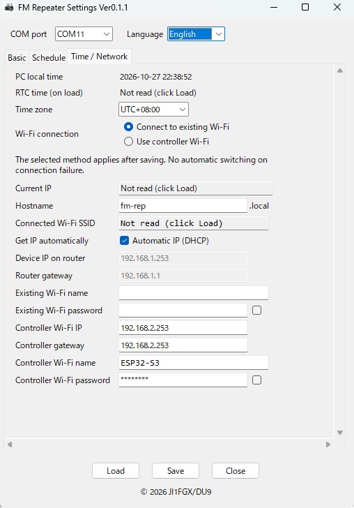
Time / Network| Screen Label | Description and Settings |
|---|
| PC local time | Displays the current PC time. |
|---|
| RTC time (on load) | Displays the controller RTC time captured when Load is clicked. Click Load if it has not been read. |
|---|
| Time zone | Select the local offset from UTC. |
|---|
| Wi-Fi connection | Select Connect to existing Wi-Fi or Use controller Wi-Fi. The selection applies after saving. There is no automatic switching on connection failure. |
|---|
| Current IP | Displays the current IP address and connection status.
This is a read-only display. Use this address to connect when DHCP is enabled. |
|---|
| Hostname | The device name on the network. For example, setting fm-rep allows access at http://fm-rep.local/ on supported networks and devices.
Do not include .local in the input field. |
|---|
| Connected Wi-Fi SSID | Displays the name of the currently connected Wi-Fi network. Click Load to retrieve it. |
|---|
| Get IP automatically | Automatic IP address assignment when connecting to an existing Wi-Fi network (STA).
Checked: DHCP; unchecked: static IP. |
|---|
| Device IP on router | Static IP address used when connecting to an existing Wi-Fi network (STA).
Used when DHCP is disabled. |
|---|
| Router gateway | Gateway for connecting to an existing Wi-Fi network (STA).
When using a static IP, enter the address of your router. |
|---|
| Existing Wi-Fi name | SSID (network name) of the Wi-Fi network to connect to. |
|---|
| Existing Wi-Fi password | Password for the Wi-Fi network to connect to. |
|---|
| Controller Wi-Fi IP | The controller IP address when it provides its own Wi-Fi network (AP).
You can connect directly even when no Wi-Fi router is available. |
|---|
| Controller gateway | Gateway field for the mode in which the controller provides its own Wi-Fi network (AP).
The current firmware uses the Controller Wi-Fi IP value as the actual gateway address. |
|---|
| Controller Wi-Fi name | Network name broadcast when the controller provides its own Wi-Fi network (AP).
Select this network in the Wi-Fi settings on your PC or smartphone. |
|---|
| Controller Wi-Fi password | Password for connecting a PC or smartphone to the Wi-Fi network provided by the controller (AP). |
|---|
Control Buttons| Screen Label | Description and Settings |
|---|
| Load | Reads the current settings from the controller and displays them. Use this before editing. |
|---|
| Save | Sends the edited settings to the controller and saves them to EEPROM. |
|---|
| Close | Closes the PC settings editor.
To keep your changes, click [Save] first. |
|---|
Start-second settings use the RTC (DS3231) clock. Check the controller clock before using voice ID or scheduled CW. |
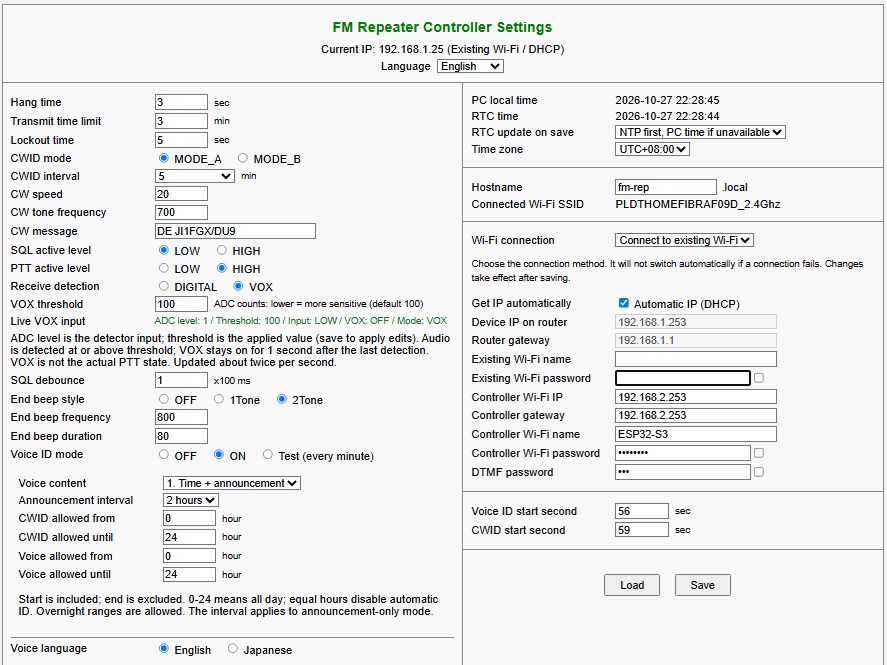
Browser Configuration over Wi-FiTo connect to an existing Wi-Fi network (STA), enter its network name in Existing Wi-Fi name and its password in Existing Wi-Fi password.
Connect your PC or smartphone to the same network to configure the controller in a browser.
In the browser address bar, enter an address such as http://fm-rep.local/ or http://192.168.1.66/.
Replace the example host name with Hostname, or use the actual address shown in Current IP.
If host-name access is unavailable, use the IP address.
To connect directly, select Use controller Wi-Fi under Wi-Fi connection and save. The controller does not switch automatically on connection failure.
In the Wi-Fi settings on your PC or smartphone, select the controller network name (Controller Wi-Fi name) and enter its password (Controller Wi-Fi password).
Then open the controller IP address (Controller Wi-Fi IP) in a browser to configure it.
After changing Wi-Fi settings, reconnect using the updated network or IP address.
|